Configuration of powder coating application equipment
There are many ways to apply powder coating materials; however, the material that is to be applied must be of a compatible type. For instance, if the method of application is fluidized bed. then the powder coating material must be a fluidized bed grade, Conversely, if the method of application is electrostatic spray, then the powder material must be an electrostatic spray grade.
Once the material is correctly selected, then the method of application is selected by part design and production goals. There are two forms of application methods. These vary as widely as the applications they suit. These forms are:
- Fluidized bed application
- Spray application.
FLUIDIZED BED
This method of application was the first one used to apply powder coating materil. It is still used today on many applications where the after cured film thickness is above 5.0 mils. Typical items are wire products, electrical bus bars, etc.
The fluidized bed method of application can be performed in two ways. One way is the . This is a process that requires preheating the part so that the powder will melt and adhere to it. The hot part is placed into a fluidized bed of powder for coating. The amount of powder that is applied to the part is a function of how hot the part is and how long it is in the bed. It is obvious that the control of film thickness is not of primary concern when this method is used.
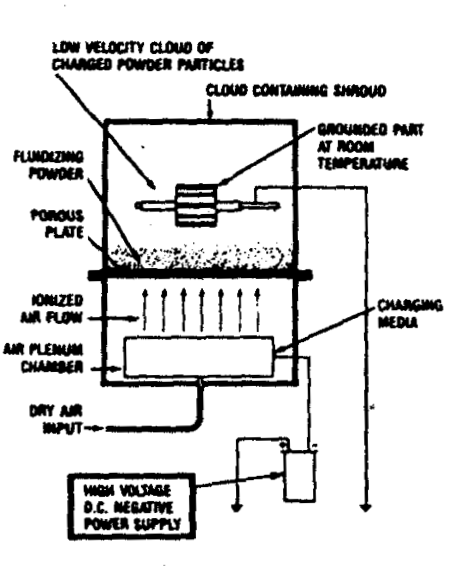
To gain more control of film thickness on the part, with a fluidized bed system, the principles of electrostatics are introduced. As shown in Fig. 1, the part is transported above the fluidized bed and the powder is attracted to it. The part now requires no preheating prior to being placed above the bed. The powder is attracted to the part by means of an electrostatic charge on the powder particle. This electrostatic charge is developed in an electrostatic field either above or in the fluidized bed.

The film thickness on the part is now controlled by not only the amount of time the part is in the fluidized bed, but also how much electrostatic charge is on the powder particle. Heat is still sometimes used in this process to overcome part configuration that may cause Faraday cage problems.
This method of application is used for coating electrical motor armatures. These require a high dielectric strength coating with film thickness control to allow the wire to be wound properly.
Fluidized bed Construction varies with each manufacturer; however, the same basic components are used in all designs. These components are the hopper or tank, the plenum or air chamber, and the fluidizing plate. Different materials are used for each of these components dependent upon design, manufacturer, and end use. For instance, the fluidizing plate can be made of porous polyethylene, sound board, craft paper, or any porous material or combination of materials. The tank can be made of whatever material that can support the weight of the powder.
SPRAY APPLICATION
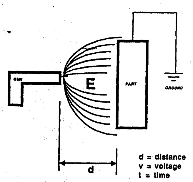
The method of applying powder coating with electrostatic spray equipment is broken down into two types. In both cases electrostatics must be used to attract the powder to the part.Tere is no mechanical attraction or adhesion to hold. The powder to the part as seen in liquid spray systems. Therefor, the powder must be charged, or the part heated (thermal attraction), to be attracted to the substrate. The best analogy to explain this is that if you rub a balloon against your hair, it will stick to the wall because of the electrostatic charge. The same balloon will not stick to the wall without the electrostatic charge. This experiment should be performed on a dry(not humid )day. The two types of electrostatic spray equipments are:
- corona charged spray guns.
- Tribo charged spray guns

Amperage limitation, current cycling or intermittent current application lengthen the required coating time, since it is the applied ampere-seconds (coulombs) which produce the electrodeposit.
Current Consumption ranges from about 15 coulombs per gram of finished coat up to 150 coul/g. After an initial amperage surge, the high electrical resistance of the freshly deposited film diminishes the current flow, resulting in an overall requirement of two to four amp per square foot for one to three minutes, or between one and three kilowatt hours per 100 square feet. Coating Time ranges usually from one to three minutes. For some special work, such as wires. steel bands, etc., coating times as low as six seconds are reported.
The voltage requirement is largely dictated by the nature of the dispersed resin in the bath. Installations are usually operated at between 200 and 400volts, though some are reportedly operated as low as 50 volts and others as high as 1000 volts.
Rinsing:
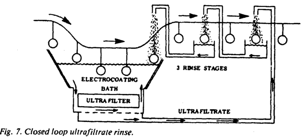
Freshly coated pieces, when lifted from the bath, carry bath droplets and even puddles of paint. A high concentration of paint solids exists in the vicinity of a work piece which is being coated. It is estimated that an automotive body may carry (drag out) about 1 gallon of bath. At 10wt% non-volatiles this is approximately 1 lb. solids. Considering the migration of solids towards surfaces which are being coated, solids concentrations of up to 35% are expected in their vicinity. Thus, it is evident that the recovery of lifted paint bath is necessary, and a lucrative way has been found in the form of “ ultrafiltrate rinse.”
Ultrafiltration uses membranes which allow the passage of water and truly dissolved substances, such as solvents, solubilizers, salts (impurities!), etc. Dispersed paint resins, pigments, etc. are retained by the membrane. One hundred or more gallons of bath pass on one side of the membrane under pressure, while one gallon of clear aqueous fluid passes through the membrane. The fluid, called permeate or ultrafiltrate, is collected and used as rinse fluid (Fig. 7). A three-stage rinse system recovers approximately 85% of the paint solids which were lifted from the bath.
Quantities of ultrafiltrate are sometimes discarded, which may necessitate trucking to dump sites. The volume of these wastes can be reduced by reverse osmosis.
Bake or Cure:
The time/temperature requirements for curing are dictated by the resin system and are similar to those required for conventional dip or spray paints – usually 5-25 minutes at 250’F to 400°F air temperature. Air-drying electrocoats are on the market.

EQUIPMENT
Coating Tanks.
Two types of tank are used:
- The tank wall is used as counter-electrode.
- The tank wall is lined with an electrically insulating coat, while the counter- electrodes are inserted in the tank and then positioned according to size or shape of work piece. The electrodes are in some installations surrounded by compartments, one side of which is formed by a membrane. The counter ions “X” or”Y”( Table 1) accumulate in the electrode compartments by a process called electrodialysis, and are discarded or reused.
Agitation:
Pumps, draft tubes, line shafts and ejector-nozzle systems capable of moving or turning over the entire bath volume in 6 to 30 minutes are used to prevent the paint from settling in the tank.
Flltration:
As a rule, 5 to 75 micron pore size filters are used to pass the entire paint volume through the filter in 30to120 minutes. The acidic feed materials are manufactured and shipped at paint solids concentrations ranging from 40% to 99+ %. In some installations, the feed is metered into the tank in the form of two or more components, one component being the resin, the other component being a pigment slurry, etc.
Solubilizer Removal Method:
T o keep a bath in operating condition, removal of leftover solubilizer is accomplished through electrodialysis, ion exchange, or dialysis methods.
Cooling Equipment:
Practically all the applied electrical energy is converted into heat. Cooling equipment must be adequate to maintain the desired bath temperature, usually between 70°F and 90F, as specified by the paint suppliers.
Bake Or Cure:
The conventional type of oven is used. The air velocity through the oven is com-paratively low, due to the very small quantities of organic volatiles in the paint coat.
Power source:
Rectifiers which deliver direct current of less than 10% ripple factor are usually specified. Various out-put voltage controls are in use, such as tap switches, induction regulators, saturable core reactors, etc. Voltages in the 50 to 500V range are usually provided. The current requirement is calculated from the weight of coating to be applied in the available time.

 D5 Creation
Comments are Closed